News and Press
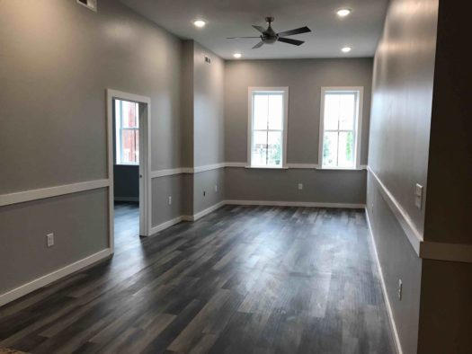
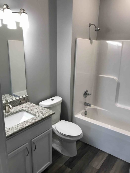
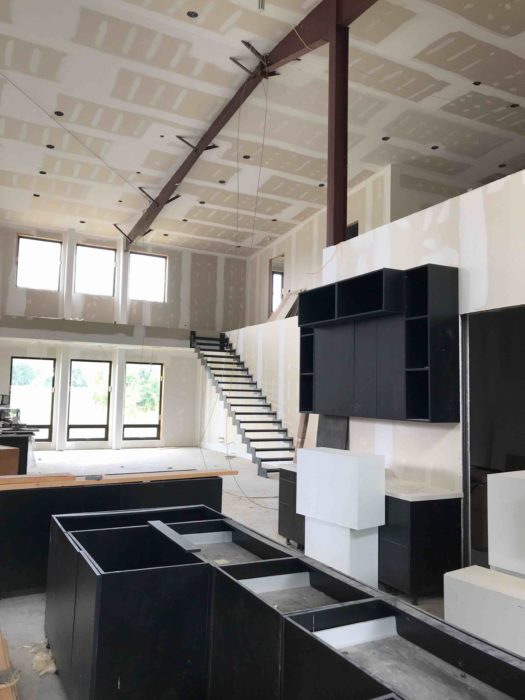
INTERIOR RENO / DOWNTOWN JOHNSON CITY


~~~~~~~~~~~~~~~~~~~~~~~~~~~~~~~~~~~~~~~~~~~~~~~~~~~~~~~~~~~~~~~~
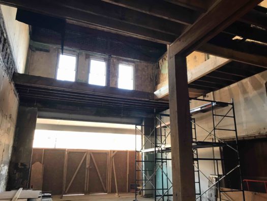
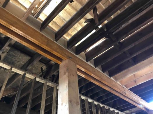
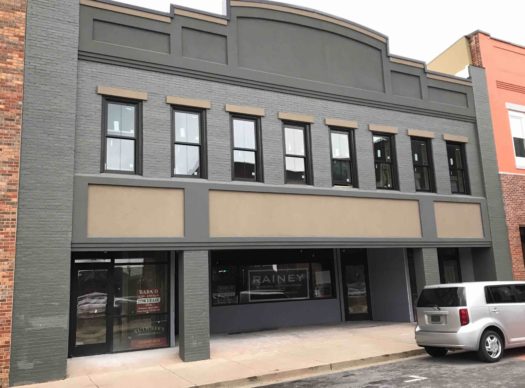
524 E ELK, ELIZABETHTON RESTORATION
~~~~~~~~~~~~~~~~~~~~~~~~~~~~~~~~~~~~~~~~~~~~~~~~~~~~~~~~~~~~~~~~~~~~~~~~~~~~~~~
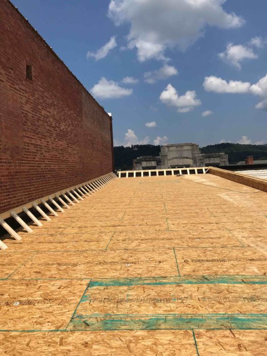
BOONE LAKE
~~~~~~~~~~~~~~~~~~~~~~~~~~~~~~~~~~~~~~~~~~~~~~~~~~~~~~~~~~~~~~~~~~~~~~~~~~~~~~~
Atlanta Braves’ SunTrust Park Hits a Home Run
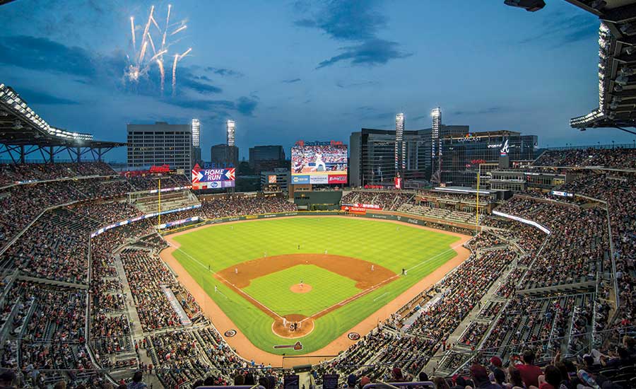
SunTrust Park
Atlanta
Best Project, Sports/Entertainment
Key Players
Owner: Atlanta Braves
Lead Design Firm: Populous
General Contractor: American Builders 2017
Project Manager: JLL
Civil Engineer: Kimley-Horn & Associates Inc.
Structural Engineer: Walter P Moore
MEP Engineer: ME Engineers
Audiovisual Consultant: WJHW
Food Service Consultant: S2O Consultants
The Atlanta Braves opened the new $500-million SunTrust Park on March 31, defeating the New York Yankees in an exhibition game. The event was not only a win for the team and its fans, it was a victory for the design, construction and development partners who delivered the construction project under one of the fastest schedules in the history of major league sports.
“To be there on the opening day and experience the joy of people having fun in a facility that you poured your heart into, you forget all of the difficult things that happened,” says Chris Britton, project director with American Builders 2017. “All of those challenges and sacrifices go away with that opening pitch.”
American Builders 2017—a joint venture between Brasfield & Gorrie, Mortenson Construction, Barton Malow Co. and New South Construction Co.—completed the ballpark in 29 months, just in time for the start of the 2017 season. The construction team and its subcontractors logged more than 5.6 million work hours on the project.
Keeping the project on track proved to be a daunting task right from the start as the team encountered site conditions that jeopardized the schedule. The team began with limited information about the 57-acre greenfield site, located at the crossing of Interstates 75 and 285 in Cobb County. Three natural gas pipelines running through the main portion of the ballpark site had to be relocated. Deep rock near home plate required blasting approximately 50 ft into the rocky areas.
Crews also encountered soft soils in the outfield, which required up to 60 days of surcharging before work could continue.
The project was initially sequenced to start at home plate and progress into the outfield. To overcome site issues, the project was resequenced to start in the outfield while the pipeline relocation and blasting continued near home plate. Teams worked in both directions around the ballpark, meeting at home plate. Ultimately, teams worked in several areas simultaneously to make up time on the schedule. At peak, 14 cranes were active on the site.
“There were many site logistics and site challenges that had to be addressed along the way,” says Mike Plant, president of development for the Atlanta Braves. “Despite encountering these challenges during construction, American Builders 2017 managed to keep the project on schedule, meeting or beating every turnover milestone date for occupancy.”
Due to the fast-track schedule, construction began while some designs were still in the schematic phase. Key subcontractors were brought on in a design-assist role to work with the design team, led by Populous, to maintain quality while protecting the budget. One of the most innovative parts of the project, the sports lighting system, resulted from the project team’s collaboration with GE in the development of its first full LED system in a major league ballpark.
The JV didn’t reach a final GMP until nine months after groundbreaking.
Working with the design team, American Builders 2017 recommended a hybrid structure of concrete and steel for the 41,500-seat stadium, featuring concrete concourses with structural steel for the raker beams and canopy structure. A main goal of the structure’s design was speed of delivery. The 37 steel raker trusses for the terrace level were prefabricated in Texas. More than 78 ft long, the rakers were shipped to the site in single pieces and picked from trucks for placement.
Crews poured more than 57,300 cu yd of concrete at the facility, which equates to more than 4,770 truckloads of concrete. The team also placed more than 5,600 tons of rebar, 6,800 tons of structural steel, 231,890 linear ft of piping, 502,000 concrete masonry units and 602,000 hand-set bricks.
The ballpark’s design incorporates brick and stone, crowned by a steel structure that supports the largest shade canopy in Major League Baseball.
The ballpark acts as the anchor of The Battery Atlanta, a 60-acre mixed-use community. The ballpark was designed concurrently with the Battery to help seamlessly meld it into a unified development. The ballpark is conceived as “the living room for the entire community,” according to Populous. Surrounding retail, residential and office spaces have views into the ballpark.
Bradd Crowley, project manager at Populous, says the strategy offered a unique opportunity to integrate with other designers. “If you’re sitting in the ballpark and looking out toward left field, it’s hard to tell where our project stopped and the other development begins,” he says. “The styles blend very well. It all came together at one time.”
~~~~~~~~~~~~~~~~~~~~~~~~~~~~~~~~~~~~~~~~~~~~~~~~~~~~~~~~~~~~~~~~~~~~~~~~~~~~~~
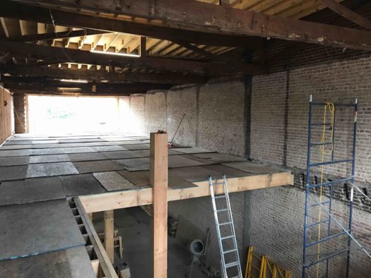
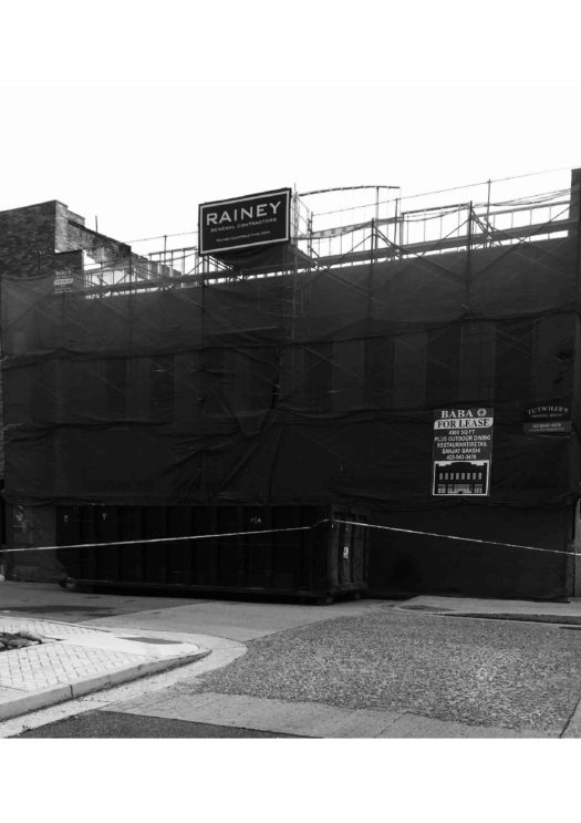
W. G. STREET, ELIZABETHTON
RAINEY GENERAL CONTRACTORS – Restoration of The Bemberg Boarding House built in 1924 is underway! This 7,000 SF building is being restored & preserved to it’s original architecture and structural design.
~~~~~~~~~~~~~~~~~~~~~~~~~~~~~~~~~~~~~~~~~~~~~~~~~~~~~~~~~~~~~~~~~~~~~~~~~~~~~~~
Steel Core System Could Transform Office Tower Construction
A radically different shear-wall core system for simpler and speedier construction of steel-framed high-rise office buildings is about to make its debut. The coupled steel-plate composite wall system—a sandwich of plates filled with concrete liberated of reinforcing steel—provides the strength, stiffness, safety and serviceability of a reinforced concrete core but is not burdened by rebar congestion and complex formwork, say structural engineers testing the system.
The sandwich wall, appropriate where either seismic or wind loads prevail, “fundamentally changes the game,” says Ron Klemencic, chairman and CEO of Magnusson Klemencic Associates (MKA) and the structural engineer pioneering its use. MKA predicts the system can slash superstructure construction time in half.
There is no time lost to install rebar—the plates serve that function. There is no formwork—the plates serve that function, as well. Absent formwork, rebar and curing time for the concrete, the core and perimeter steel can rise in concert, rather than the slower core leading—and delaying—the quicker steel, says Klemencic.
Another plus is that core wall sections are prefabricated into modules, complete with tie rods that separate the plates and shear studs. And the modular walls do triple duty as falsework for construction loads before the concrete filling is added.
The conventional hybrid system—a reinforced concrete core with perimeter steel columns and floor systems of steel beams supporting a composite metal deck—also results in tolerance issues where the beams connect to the core. Steel tolerances, set by the American Institute of Steel Construction (AISC), are tighter than concrete tolerances, set by the American Concrete Institute. Under the steel-plate system, steel connects to steel, eliminating tolerance issues and overlapping trade issues.
Faster, Simpler, Safer
All told, construction is faster, simpler and safer than it is with a hybrid system, says Klemencic. “If successful, the new approach will transform the marketplace,” he predicts.
A $600,000 study, jointly sponsored by the Charles Pankow Foundation and AISC, is under way to adapt the composite steel walls—first used in the U.S. in the nuclear powerplant sector because they are virtually impenetrable—for high-rise buildings.
Tests were needed for commercial applications because nuclear structures have long squat walls, dominated by shear, and high-rises have tall slender walls, dominated by flexure, says Amit H. Varma, director of the Robert L. and Terry L. Bowen Laboratory at Purdue University, which is conducting the three-year research program in conjunction with the University at Buffalo. Varma, who began testing the system in 2005 for nuclear powerplants, is principal investigator for the current study, working with UB’s Michel Bruneau.
The research is subjecting six specimens to axial force and cyclic lateral loading and evaluating the structural behavior, including stiffness, strength and drift capacity. The specimens have different variables, such as spacing and numbers of cross rods and shear studs.
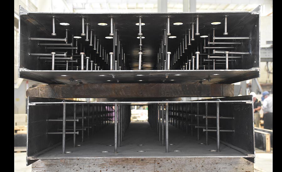
 Preliminary results of the first of six physical tests on coupled steel-plate composite shear-wall specimens indicate excellent behavior and cyclic performance. Photo Courtesy of AISC Preliminary results of the first of six physical tests on coupled steel-plate composite shear-wall specimens indicate excellent behavior and cyclic performance. Photo Courtesy of AISC |
The goal is to generate experimental data and numerical models that will provide insights into the behavior of the system and allow the development of seismic and wind design provisions. “We are trying to optimize the design so it becomes more cost effective,” says Varma.
The team completed the first physical test late last month. Preliminary results indicate “excellent behavior and cyclic performance of the specimen,” says Varma.
The limit states are as expected, but the specimen strength is even greater than that calculated using simple methods, code equations or even finite element models, he adds.
Five more tests will be conducted at Bowen to evaluate the influence of parameters such as the axial load level, tie bar spacing and the use of shear studs along with tie bars.
Limitations
The sandwich does have some limitations. It is easier to cut into concrete in the field. With the steel wall system, it is best to plan, coordinate and detail all openings before shop fabrication, says Klemencic.
In addition, there are issues relating to detailing the module-to-module connections and the design and detailing of the coupling beams that separate and link modules to create doorways and other large spaces between modules.
Also, the system is not covered in the prescriptive provisions of the building codes. To date, to use it, engineers must do performance-based design, which requires peer review.
The AISC steel specification addresses the walls, based on research performed for the nuclear powerplant sector. The new studies will result in expanded information in AISC specifications, says Varma.
In addition to the Purdue-UB research, AISC and the Pankow Foundation are co-funding a FEMA P-695 computational study at UB, also with Purdue, set to wrap up next year. Researchers expect that coupled systems are more ductile and have more redundancy, but the American Society of Civil Engineers (ASCE), which develops the design standard for structures, currently does not assign coupled systems higher seismic response factors, called R-factors.
This study uses the FEMA P-695 methodology to substantiate the R-factors for the sandwich system. The additional research, costing $166,000, is expected to demonstrate that the sandwich systems are rated with the highest R-factor of any shear wall system of any material—an R-8 factor, says Lawrence F. Kruth, AISC’s vice president for structural engineering and research. The seismic factors developed will eventually be incorporated into the ASCE structural standard—known as ASCE 7.
Regarding the Bowen tests, Varma expects to have test data on the first six specimens by the end of the year. The second phase of testing, at UB, will begin on C-in-plan-shaped walls, which consist of three connected wall modules. The final tests, at Purdue, will be on composite dual-plate coupling beams, which, like doorway headers, connect separated modules and dissipate energy during an earthquake. The $600,000 study concludes in 2019.
“The goal is to have the wind design provisions in the main AISC specification and the seismic design provisions in the AISC seismic specification,” probably by 2022, says Varma.
First Use
MKA is eagerly anticipating the research results, which it hopes will support less-expensive walls with fewer ties. But it is not waiting for the design guidance to move on the first use of the system in a tall building. It already has approval to use the system in an 850-ft-tall office and residential tower in Seattle, set to start construction in January. Absent the research, MKA’s performance-based design for the tower, called Rainier Square, is conservative.
Klemencic figures the system is most cost-effective for a building 40 stories or taller, mostly based on the required thickness of the steel plate. For the 58-story Rainier Square project, the team, which includes Lease Crutcher Lewis as the contractor, the Supreme Group as steel fabricator and the Erection Co. as the steel erector, is working out the construction details by building a full-scale mock-up.
The team expects to have the self-consolidating concrete filling—cast a floor at a time through openings at the tops of the walls—trail all the structural steel framing by four floors. The plan is to field-weld the modules together. Klemencic expects the building to be finished by late 2020.
The hope is that, as a result of the research, the next high-rise using the system will be more refined in its design and more efficient and economical, says Klemencic.
~~~~~~~~~~~~~~~~~~~~~~~~~~~~~~~~~~~~~~~~~~~~~~~~~~~~~~~~~~~~~~~~~~~~~~~~~~~~~~
Investigators Explain Focus On Pre-Collapse Cracking In Florida Bridge
A final determination of the deadly accident’s cause could take 24 months
The National Transportation Safety Board’s preliminary report on the fatal collapse in March of a pedestrian bridge at Florida International University in Sweetwater focuses attention on the widely discussed pre-collapse cracking in the main span. The report also confirms accounts about what the construction crew working on the bridge was doing before the structure fell.
But the report contains no definitive explanation of what occurred and months and possibly years more will be needed to determine the probable cause of the failure, which killed five motorists and one project worker.
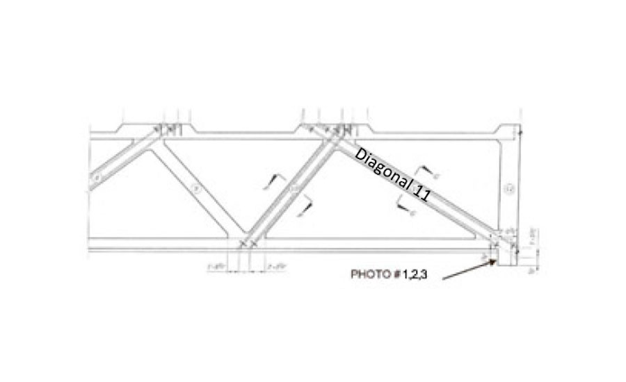
Issued May 23, the NTSB report states that while the board “is evaluating the emergence of cracks” in diagonal members located at both ends of the bridge, it is also studying “the propagation of cracks” near diagonal member 11, located at the structure’s north end.
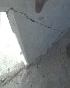 |
| Photo 1: An image accidentally released by the National Transportation Safety Board earlier this month to the Miami Herald showing a crack in the region of bridge diagonal 11. |
A video of the collapse appears to show the failure starting at that part of the concrete truss bridge’s main span.
Seven vehicles beneath the 174-ft-long bridge were occupied at the time of the collapse early in the afternoon of March 15. The partially constructed pedestrian bridge was being built by a design-build joint venture called MCM-FIGG, consisting of contractor MCM Construction and FIGG Engineers, both based in Florida.
Following the design plan, construction crews five days prior to the collapse were “de-tensioned the bridge diagonal members on the north and south ends of the bridge,” the report states. On March 15, the day of the accident, a construction crew was busy “re-tensioning the number 11 diagonal member connecting the canopy and the deck at the north end of the bridge,” states the report.
 |
| Photo 2: A second photo of a crack in the region of diagonal 11 of the failed Florida International University pedestrian bridge. The cracks are a focus of federal investigators. |
Much speculation about the cracks has been published.
The project team’s knowledge of pre-collapse crackingin the bridge span was first reported on March 16, when the Florida Dept. of Transportation (FDOT) released the transcript of a voicemail it had received from the bridge project’s lead engineer prior to the collapse.
According to FDOT’s transcript of the voicemail, Denney Pate, of FIGG Bridge Engineers, tells the agency that the project team had “taken a look at (the cracking.”
Pate then added, “Obviously some repairs or whatever will have to be done but from a safety perspective we don’t see that there’s any issue there so we’re not concerned about it….”
Additionally, FIU acknowledged, the project team had met for more than two hours to discuss the cracking issue on the morning of the collapse.
FIGG Bridge Engineers says that it can’t comment on the interim report and that it is cooperating with the NTSB on its investigation, which “is still in the early fact-finding stages.”
Moving forward, NTSB plans to conduct “additional forensic examination of several bridge structural components and destructive testing of multiple core and steel samples.”
Also, the agency stated that “all aspects of the collapse remain under investigation,” including the bridge design plans.
Lawsuits and Liability
A final report on the FIU bridge collapse—which will include determination of a probable cause plus recommendations to avoid future accidents—likely won’t come until 2019, or possibly 2020, says the NTSB. Investigations involving fatalities usually take between 12 and 24 months to complete, the board stated.
One of the first lawsuits—filed on behalf of FIU student Emily Joy Panagos, whose car was crushed—suggests that post-tensioning triggered the failure that brought down the structure. The lawsuit alleges that the post-tensioning compressed the diagonal so that it overstressed a joint in the top chord, triggering hinge failure at a connection in the lower chord and resulting in the catastrophic failure of the rest of the 174-ft-long structure.
Aside from the technical aspects of the tragedy, the legal and financial ramifications are likely to be severe.
One possibility, legal experts say, is that the two companies in the design-build joint venture—MCM actually employed FIGG on the project—will end up squaring off over the costs.
FIGG’s liability could hinge partly on whether it recommended, designed or supervised the work involving tension rods or cables being performed on the bridge the day of the collapse.
“When it comes to liability of a design-build joint venture, and the team is jointly and severally liable, within the team there will be what are called indemnity contribution claims,” says Judah Lifschitz, an attorney who is a partner in Washington, D.C.-based Shapiro, Lifschitz and Schram. “And each party will have its own insurers.”
The companies and insurers involved in a costly accident, says Lifschitz, “often look to the other companies, such as their subcontractors and suppliers, to share the pain.”
~~~~~~~~~~~~~~~~~~~~~~~~~~~~~~~~~~~~~~~~~~~~~~~~~~~~~~~~~~~~~~~~~~~~~~~
VA Medical Center – Emergency Department Expansion
RAINEY GENERAL CONTRACTORS – Emergency Department for Veterans Affairs Medical Center at Mountain Home
Sabine Hill Restoration
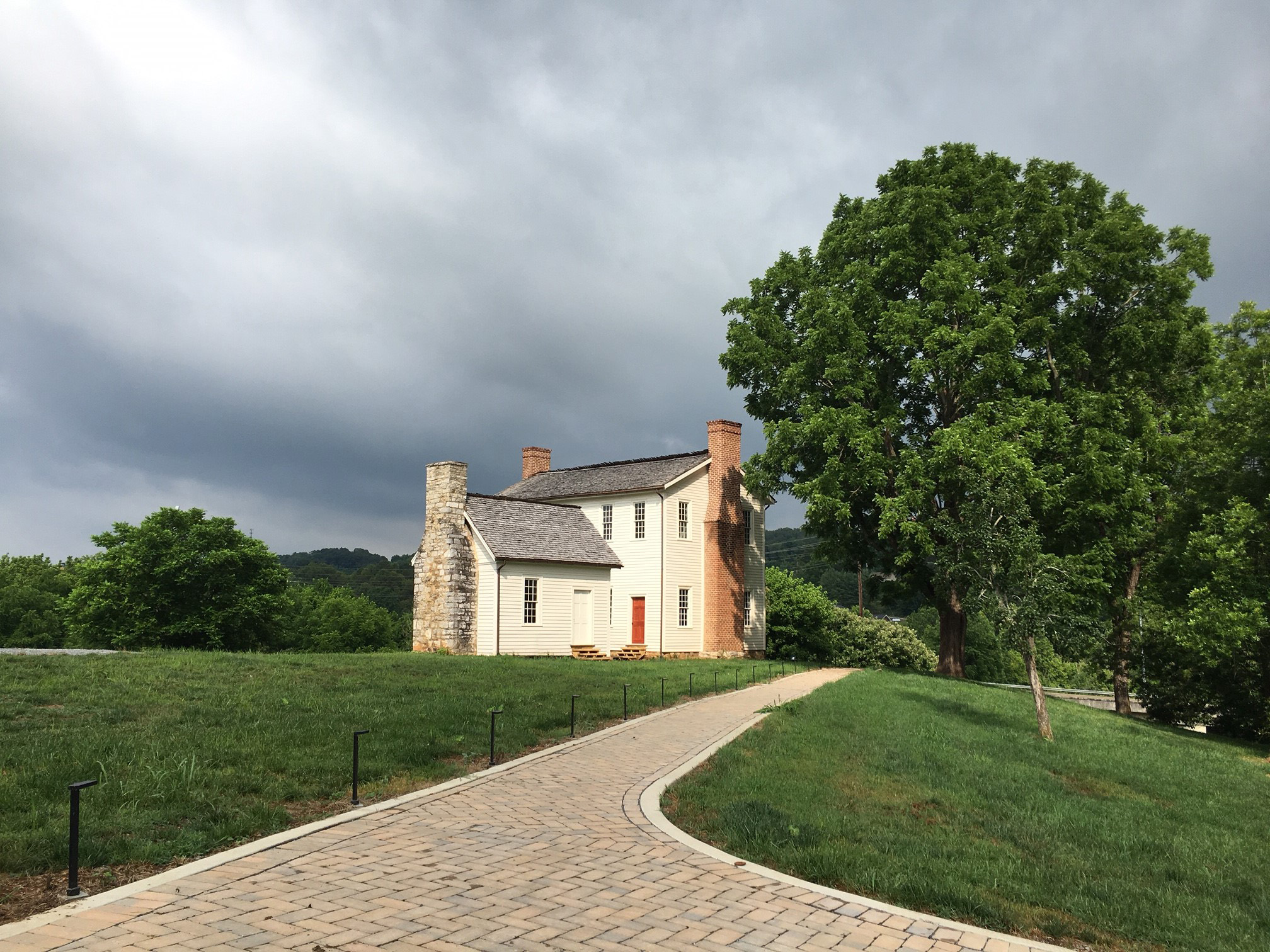

RAINEY GENERAL CONTRACTORS – Sabine Hill Historic Estate in Elizabethton, TN.
Brigadier General Nathaniel Taylor began building Sabine Hill between 1814 and 1816, after returning home to Elizabethton following the War of 1812.
https://en.wikipedia.org/wiki/Sabine_Hill
An historic home once doomed for destruction is about to experience a million dollar re-birth.